| Back to Index |
I'll be honest, I didn't tackle this week's assignment of "Pick a programming language, talk to a device, build an interface, add some graphics, execute the interface." I attended class last week, and while I found the session very interesting and informative, I am FAR from comfortable working with programming, and the assignment for the week felt WAY over my head. Combine that with Thanksgiving travel, plus the fact that I don't yet have an FTDI-to-USB converter to connect my TxRx board to my computer (I have ordered one!), plus the fact tjhat most of my Harvard projects are due this week, all left me feeling that attempting to program an application, plus graphics, was a bit more than I could handle. I know where to start should I ever need to make an interface app, but this was not the week to start it.
However, as I'm not usually one to just not do my homework, I decided to compromise, and spend the week getting more comfortable programming my RGB LED in preparation for my final project. At the end of last week, I had just gotten my RGB to light up and show SOME colors, but I did not feel in control of WHICH colors it was showing, nor why. That would be important for my final project.
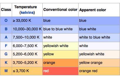
A reminder: my final project will allow a user to experience how different pressures in the core of stars cause stars to burn at different temperatures, and therefore different colors, as seen in the below chart (borrowed from here:
I had wanted to capture orange (R=255, G=165, B=0), but I realized orange would naturally happen as the green LED fades from off to full on, on the way from red to yellow (R=255, G=255, B=0). So there was a smooth progression of color I wanted to simulate:
Red = 255
Green = PWM from 0 to 255
Blue = 0
Red = 255
Green = 255
Blue = PWM from 0 to 255
Red = PWM from 255 to 0
Green = PWM from 255 to 0
Blue = 255
So I started playing around with my RGB code, to create a nice smooth flow through that sequence of color. I confirmed my suspicion from last week that, because of the common anode arrangement of my LEDs, "set" and "clear" needed to be reversed.
When I ran Neil's code (below) on my board, instead of Red fading in, it started at full and faded out:
for (count = 0; count < 255; ++count) {
clear(led_port,red);
for (pwm = count; pwm < 255; ++pwm)
PWM_delay();
set(led_port,red);
for (pwm = 0; pwm < count; ++pwm)
PWM_delay();
}
By swapping "clear" and "set," I got Red to fade in nicely on my board. I also figured out that, even though Rob in the Harvard shop told me that each individual "for" loop (as seen above) operate independently of each other, and color from one wouldn't carry over into the next, that didn't seem to be the case on my board. At one point, once Blue was turned on, it didn't turn off when the main loop reset. What should have restarted with a solitary Red was now bright purple. However, since my desired color sequence more or less needs LEDs to come on and stay on, I figured out that if I put some "set"s in between each "for" loop, the desired color would stay on. Here's what I ended up with:
while (1) {
//
// Red fades in
//
for (count = 0; count < 255; ++count) {
set(ledr_port,red);
for (pwm = count; pwm < 255; ++pwm)
PWM_delay();
clear(ledr_port,red);
for (pwm = 0; pwm < count; ++pwm)
PWM_delay();
}
clear(ledr_port,red);
//
// Green fades in, making Orange then Yellow
//
for (count = 0; count < 255; ++count) {
set(ledgb_port,green);
for (pwm = count; pwm < 255; ++pwm)
PWM_delay();
clear(ledgb_port,green);
for (pwm = 0; pwm < count; ++pwm)
PWM_delay();
}
clear(ledgb_port,green);
//
// Blue fades in, making white
//
for (count = 0; count < 255; ++count) {
set(ledgb_port,blue);
for (pwm = count; pwm < 255; ++pwm)
PWM_delay();
clear(ledgb_port,blue);
for (pwm = 0; pwm < count; ++pwm)
PWM_delay();
}
clear(ledgb_port,blue);
//
// Green and Red fade out, leaving Blue
//
for (count = 0; count < 255; ++count) {
clear(ledgb_port,green);
clear(ledr_port,red);
for (pwm = count; pwm < 255; ++pwm)
PWM_delay();
set(ledgb_port,green);
set(ledr_port,red);
for (pwm = 0; pwm < count; ++pwm)
PWM_delay();
}
//
//Blue fades out
//
for (count = 0; count < 255; ++count) {
clear(ledgb_port,blue);
for (pwm = count; pwm < 255; ++pwm)
PWM_delay();
set(ledgb_port,blue);
for (pwm = 0; pwm < count; ++pwm)
PWM_delay();
}
}
}
With my color sequence figured out, my major challenge is going to be figuring out how to keep the PWM proportional to data from the step response. I *think* this is what my final code will basically look like:
Step response code, which generates values (SRV) between, say, 0 and 400, with 0 being far apart, and 400 being the capacitor pads touching.
If 0 < SRV < 100 (when the two spheres encasing the pads touch)
Then: ALL LEDs = 0
If 101 < SRV < 200
Then:
R = 255
G = PWM from 0 to 255, proportional to SRV range
B = 0
If 201 < SRV < 300
Then:
R = 255
G = 255
B = PWM from 0 to 255, proportional to SRV range
If 301 < SRV < 400
Then:
R = PWM from 255 to 0, proportional to SRV range
G = PWM from 255 to 0, proportional to SRV range
B = 255
So there's some math to figure out, and some code to figure out, but I'm pretty sure that's the general shape my code needs to take. I have until December 20 to make it work!